Highlight
Every project tells a story — of clarity in planning, precision in execution, and trust built along the way.
Here is a glimpse into the solutions we’ve built, and the impact they continue to create.
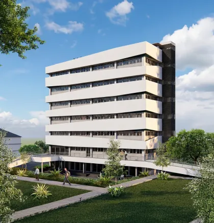
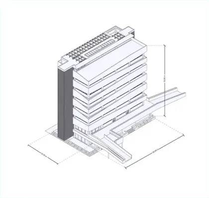
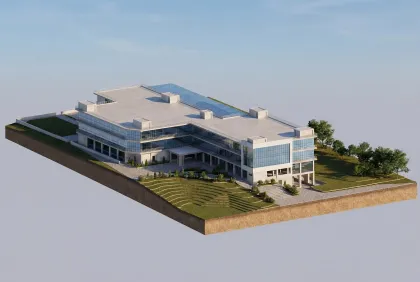
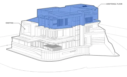
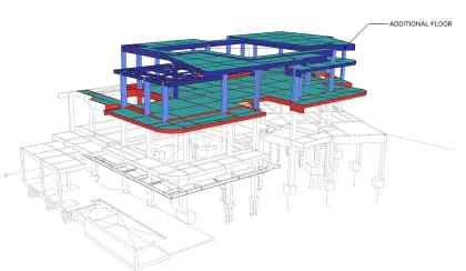
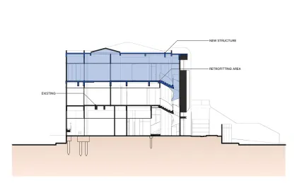
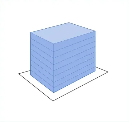
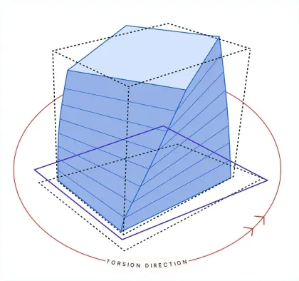
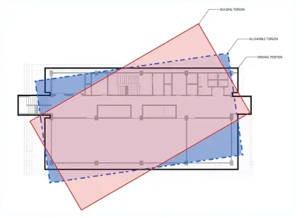
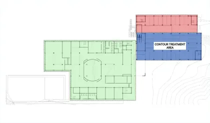
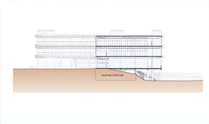
One of the requirements in high-rise building structural design involves structural analysis checks. Inter-story drift is a key control parameter that must be maintained within maximum limits. A consequence of building drift is torsional irregularity. Horizontal torsional irregularity occurs because the building's center of mass and center of rigidity are not aligned, particularly when the building is subjected to lateral forces.
In this specific case, the horizontal torsional irregularity exceeds the allowable limits and falls under Type 1b, where the maximum story drift is greater than 1.4 times the average inter-story drift. Consequently, several design stages and the application of additional loads—in accordance with SNI clauses—must be reiterated until the entire structure complies with all structural analysis control requirements.
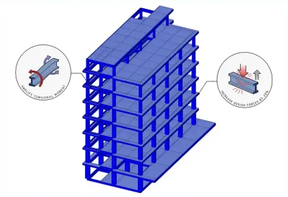
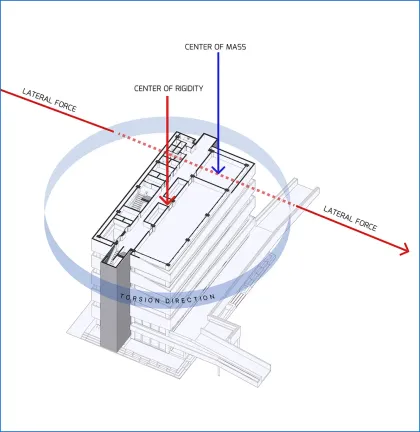
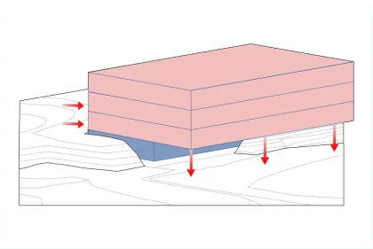
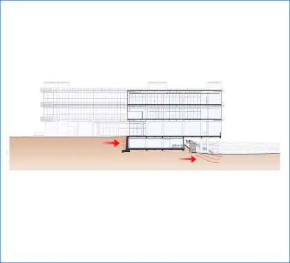
Mitigating Torsional Irregularity—a critical condition where the building's Center of Mass (where seismic forces act) is misaligned with its Center of Rigidity. During an earthquake, this offset creates a dangerous "twisting" effect (torsion), threatening the integrity of both the primary structure and non-structural elements like facades.
Strict adherence to SNI (Indonesian National Standard) codes. We rigorously control Inter-story Drift to ensure the maximum displacement at any story does not exceed 1.4 times the average displacement. Exceeding this threshold classifies the structure under "Torsional Irregularity Type 1b," requiring immediate and complex design interventions.
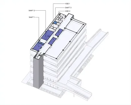
Strategic optimization of structural rigidity. By reconfiguring shear walls and columns, we align the Center of Mass with the Center of Rigidity as closely as possible. This engineering balance ensures a stable structure that not only passes regulatory compliance but remains functional and safe following seismic events.
Emergency staircases are a building’s last line of defense in critical situations. For this reason, their placement and design must be determined from the earliest design stage. According to Indonesian National Standards (SNI), emergency stairs are essential life-safety elements, not optional additions. Proper planning includes adequate stair width, safe evacuation coverage, fire-resistant materials, and clear emergency lighting and signage.
These decisions also affect structural design and MEP systems, influencing beams, slabs, electrical supply, ventilation, and safety infrastructure. When emergency staircases are not coordinated early, projects often face major design revisions and increased costs. Integrating them from the beginning ensures safer evacuation, smoother coordination, and a more efficient building design overall.
Emergency stairs are a critical safety element mandated by SNI standards. To ensure effectiveness, we prioritize their placement during the preliminary design phase, rather than treating them as an afterthought.
We meticulously calculate dimensions and service radii to guarantee optimal evacuation flow. Crucially, we coordinate early with Structural and MEP teams to align structural voids and utility routes. This proactive integration prevents major design conflicts, ensures fire integrity, and eliminates costly revisions during construction.
Building on uneven contours creates varying foundation elevations. Conventional analysis (assuming rigid/fixed supports) often fails to capture the actual shear force distribution in these conditions, leading to inaccurate foundation planning.
Soil-Structure Interaction (SSI) We move beyond static assumptions by adopting the Soil-Structure Interaction method. By modeling pile foundations as "springs" rather than rigid points, and iterating calculations with geotechnical engineers, we capture the realistic flexibility of the soil. This results in a foundation design that is not only safer but also highly efficient and tailored to the specific site topography.
For 24/7 facilities like Control Rooms, standard MEP planning is insufficient. We dive deep into the specific operational needs—from server cooling and redundancy power to complex plumbing requirements.
We implement rigorous Hazard Identification (HAZID) protocols during the planning stage. By collaborating closely with the end-users—who understand the daily operational risks best—we translate their insights into a robust MEP system designed for non-stop maintainability and operational continuity.
Structural retrofitting is a critical process for existing buildings that are planned to be modified — whether to improve functionality, add new loads (such as additional floors), or comply with updated seismic safety standards. This process is not simply about patching or repairing elements. It is a comprehensive re-engineering effort based on scientific principles, structural analysis, and applicable engineering standards.
The most important stage of retrofitting is the initial assessment of the existing structure.
This includes the collection of secondary data and a thorough evaluation of current building conditions:
• As-Built Drawings: Original working drawings are required to understand the existing structural system and design intent.
• On-Site Structural Assessment: Engineers conduct both non-destructive and destructive testing to determine the actual condition of the structure, including:
◦ Material Strength: Testing the compressive strength of existing concrete and reinforcement steel properties.
◦ Visual Condition: Identifying visible cracks, deterioration, or defects in structural elements such as columns, beams, slabs, and foundations.
◦ Foundation Evaluation: Reviewing the condition and load-bearing capacity of the existing foundation system.
All assessments must comply with Indonesian National Standards (SNI) to ensure data accuracy and reliability.
Once accurate field data is obtained, structural engineers perform a performance analysis of the existing building.
Using verified material properties, the structure is modeled and analyzed to evaluate its capacity to resist:
• Existing loads
• Additional planned loads
• Seismic forces according to current regulations
This analysis determines whether strengthening is required — and identifies precisely which structural elements must be upgraded.
Expert Insight:
◦ Strengthening decisions must always align with the client’s design intent. For example, if a two-storey building is planned to be expanded into three storeys (as in the Susan Project case), the analysis focuses on whether columns, beams, and foundations can safely support the added loads.
After defining the required strengthening scope, appropriate technical solutions are selected, such as:
• Steel jacketing
• Carbon fiber wrapping (FRP)
• Foundation enlargement or reinforcement
This stage requires close coordination between the structural engineer, architect, and building owner to ensure architectural plans — such as additional floors — can be realized safely through proper structural detailing.
By following these systematic steps, the modified building not only meets its new functional requirements but also achieves long-term structural safety and performance.
In construction projects—especially mid-rise buildings with moderate to high complexity—coordination between disciplines is the key to success. Building Information Modeling (BIM) is a technology that goes beyond drawings; it creates a comprehensive digital information model of the entire project before physical construction begins.
The greatest advantage of BIM is its ability to perform automated clash detection.
In conventional 2D drawings, conflicts between MEP pipes, structural beams, and HVAC ducts are often overlooked and only discovered during construction.
BIM identifies and resolves these issues early in the design phase. As a result, we no longer need to demolish or cut structural elements mid-project due to clashes between structural and MEP systems — saving significant time and costly rework.
BIM provides a data-rich 3D model.
Material quantity calculations become highly accurate. We know exactly how many cubic meters of concrete, how many meters of cable, or how many tons of steel are required.
This precision minimizes material waste and ensures procurement is delivered on time and in the correct quantities. Delays caused by material shortages — or excess stock that increases costs — can be effectively avoided.
BIM offers clear 3D visualization, making designs easier to understand for all parties, including non-technical stakeholders.
The BIM model can be integrated with the construction schedule to create 4D BIM, allowing us to simulate construction sequences virtually.
This helps identify potential bottlenecks and plan resource allocation more effectively.
As a result, construction timelines become more predictable and efficient, enabling projects to be completed on schedule — or even faster — while maintaining budget control.
Menara Rajawali, Level 7-1
Kel. Kuningan Timur
Kec. Setiabudi, Jakarta Selatan
DKI 12950